Ford 5.4 3V Head Bolt Torque Pattern and Angle Stages
Ford 5.4L 3V head-bolt guide: new TTY bolts at 30 lb-ft, then 90° and 90°, plus dry-gasket, surface, crank-position and VCT timing precautions.
For the cited 2004–2006 Ford F-150 5.4L three-valve applications, install new torque-to-yield cylinder-head bolts and tighten them in the Ford bank-specific sequence to 40 N·m (30 lb-ft), then repeat the sequence adding 90 degrees, then repeat it adding another 90 degrees. Install the correct coated head gasket dry, keep the crank in the workshop-manual service position, and never reuse the removed production bolts. Verify the exact VIN/model-year WSM before applying these stages to another 5.4L 3V vehicle line.
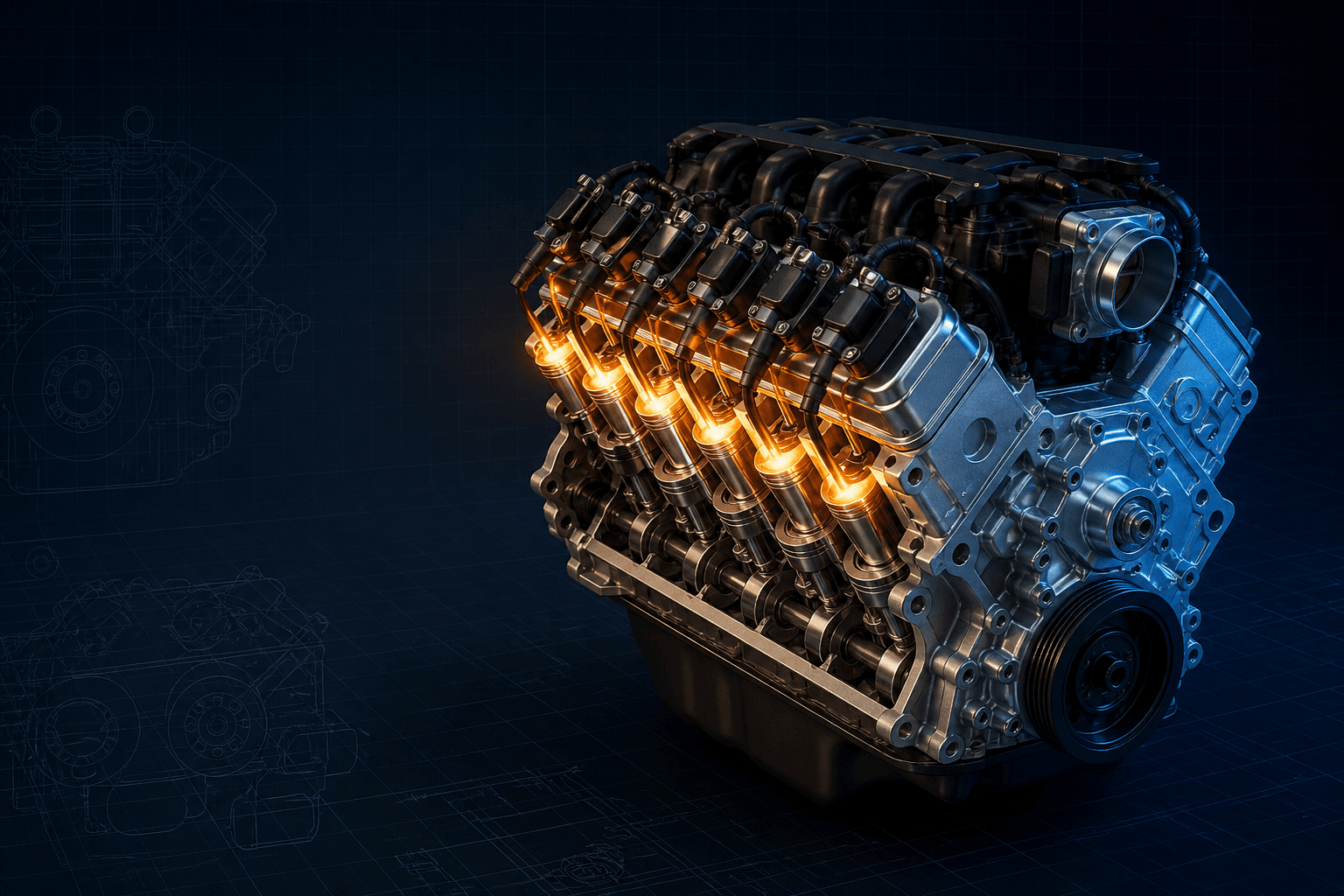
The Ford 5.4L three-valve engine combines aluminum cylinder heads, long torque-to-yield fasteners and a variable-cam-timing system. The factory head-bolt numbers are simple to repeat—30 lb-ft, 90 degrees, another 90 degrees—but the joint will not seal correctly if the gasket coating is damaged, a bolt hole contains coolant or the wrong left/right sequence is used.
Engine naming matters. Ford also built 5.4L two-valve, four-valve and supercharged variants, and generic parts catalogs may group them together. The three-valve engine is identified by its head and VCT/phaser system, then narrowed by VIN and model-year workshop information. A torque value copied from a 2V Expedition or specialty 4V engine is not validation.
The interactive graphic is a quality-control tool for recording passes, not a substitute for Ford's physical pattern. This page remains indexable but visibly limited until licensed left- and right-bank figures are attached. Keep the actual WSM figure open and mark the job card after each completed fastener.
Interactive 5.4L 3V head-bolt pass controller
Branded downloads includedPNG and PDF exports carry the TorqueSheet logo, torquesheet.com, source-page URL, and republishing attribution request. The PDF source link is clickable.
Tracks the numbered main-bolt passes; it is not a scaled physical LH/RH drawing. Map every position to the VIN-specific Ford WSM figure before tightening.
Ford 5.4 3v Head Bolt Torque Pattern Diagram
| APPLICATION / ITEM | SPECIFICATION | NOTES |
|---|---|---|
| Head-bolt stage 1 | 40 N·m (30 lb-ft) | Complete exact Ford order |
| Head-bolt stage 2 | +90° | Repeat the full sequence |
| Head-bolt stage 3 | +90° | Final production-bolt angle pass |
| Production bolts | New TTY fasteners only | Discard every removed head bolt |
| Gasket condition | New, coated and dry | No copper spray, glue or aviation cement |
The torque pattern is only one part of a 5.4L 3V head job. Aluminum surfaces cannot tolerate aggressive abrasive cleaning, the chains and cam phasers must be assembled with dedicated positioning tools, and coolant/debris must be removed from the block and cylinders. Aftermarket studs or heads use their own lubricant, washer and torque instructions.
How to use this specification correctly
- 01
Decode the VIN, engine code, model year and vehicle line. Inspect the heads and VCT hardware to confirm a 5.4L three-valve engine rather than a 2V, 4V or swapped assembly.
- 02
Before removing chains or heads, use the Ford crank and cam holding procedures. Record cam/crank correlation faults and oil-pressure symptoms so a phaser or lubrication problem is not mistaken for head-gasket failure.
- 03
Allow the aluminum heads to cool fully. Remove bolts in the published release order, then discard the old head bolts and gaskets; production bolts are tighten-to-yield and cannot be reused.
- 04
Cover open passages and clean the block and head with approved silicone-gasket remover, metal surface preparation and a plastic scraper. Do not use metal scrapers, wire brushes or powered abrasive discs.
- 05
Measure the aluminum head and block sealing surfaces by the exact Ford method. Do not assume conventional milling is approved; Ford's cited procedure gives a strict localized flatness/scratch criterion and directs replacement when limits are exceeded.
- 06
Remove coolant, solvent and foreign material from bolt holes, bores and oil passages. Inspect dowels and test new bolts for correct part number and unobstructed thread engagement.
- 07
Install the correct new coated gasket dry over the dowels, then lower the head without scraping the coating. Position the crank exactly as the WSM directs and do not rotate it until instructed.
- 08
Install new factory-type head bolts loosely and label the correct RH or LH sequence. Tighten every numbered position in order to 40 N·m (30 lb-ft).
- 09
Zero a torque-angle gauge at each bolt and repeat the full order, adding 90 degrees. Mark completed positions and keep the tool square so socket windup does not corrupt the reading.
- 10
Repeat the order once more, adding the final 90 degrees. Complete the timing chains, guides, tensioners and cam phasers using their separate Ford procedures, hand-rotate and verify timing, then pressure-test oil and cooling systems before normal load.
Why new bolts and two angle passes are required
The first 40 N·m pass seats the gasket and establishes a consistent starting load. The two measured rotations then stretch each new long bolt into its designed clamp range with less dependence on thread friction than a single high torque value.
A used torque-to-yield bolt has already experienced that controlled stretch. Ford explicitly requires discarding it, so visual appearance or relaxed-length comparison is not a basis for reuse.
Dry gasket and aluminum-surface rules
Ford prohibits aviation cement, copper spray and glue because the new gasket carries a functional sealing coating. The coating must remain dry, clean and unscratched while the head passes over its dowels.
A powered abrasive disc can make a surface look clean while cutting valleys, rounding edges and embedding grit. Ford's chemical/plastic method preserves the geometry and prevents debris from entering oil-controlled VCT components.
Crank position, chains and cam phasers
The installation procedure positions the crank with a special tool and warns not to rotate it until directed. This keeps pistons away from vulnerable valve positions while the chains and heads are being assembled.
Ford's 3V phaser bulletin treats phaser alignment and retaining-bolt tightening as a separate high-consequence operation. Head-bolt completion does not prove valve timing; align colored links and sprocket marks, release tensioners and verify rotation exactly as the WSM states.
Aftermarket studs and repaired blocks
A stud kit changes thread lubricant, under-nut friction, washer interfaces and often tightening stages. Use the exact kit sheet and cylinder-head maker's sequence; never add Ford's angle turns after an aftermarket torque value.
Thread inserts, deck machining or replacement heads also change the assembly record. Confirm insert depth, dowel height, surface finish, gasket compressed thickness and piston-to-valve clearance with the engine builder.
5.4L 3V installation checklist
- VIN/year/vehicle line and 3V identity confirmed
- 2V/4V and specialty procedures excluded
- Engine fully cool before head removal
- Old TTY bolts and gaskets discarded
- Surfaces cleaned without metal abrasives
- Head and block measured by Ford method
- Bolt holes and cylinders clean and dry
- Correct dowels and coated gasket installed
- No unapproved gasket sealer applied
- Crank in WSM service position
- Correct RH/LH sequence figure visible
- 40 N·m pass logged
- First +90° pass logged
- Second +90° pass logged
- Chains, tensioners and phasers independently verified
- Engine hand-rotated before starter use
Ford 5.4L SOHC 3-valve Modular V8 specifications can change by model year, engine, platform, wheel, and installed component. Confirm the VIN or engine identity, part numbers, fastener condition, and the current manufacturer instructions before service.
Ford 5.4 3V Head Bolt Torque Pattern and Angle Stages FAQs
What are the stock Ford 5.4L 3V head-bolt stages?+
For the cited F-150 applications: new bolts, 40 N·m (30 lb-ft), then +90 degrees, then another +90 degrees in the Ford sequence.
Can 5.4L 3V head bolts be reused?+
No. Ford calls them tighten-to-yield and requires new bolts during cylinder-head installation.
Should sealant be sprayed on a 5.4L 3V head gasket?+
No for the production coated gasket. Ford says install it dry and prohibits copper spray, glue and aviation cement.
Is the 5.4L 2V procedure the same as the 5.4L 3V?+
Do not assume it is. Identify the cylinder-head/valvetrain architecture and retrieve the VIN- and year-specific workshop procedure.
Can a final torque number replace the two 90-degree turns?+
No. Torque-angle is the specified production method and an observed final torque varies with friction.
Does correct head torque guarantee correct cam timing?+
No. The chains, guides, tensioners and VCT phasers have separate alignment and fastener procedures that must be completed and verified.
Do aftermarket head studs use Ford's 30 +90 +90 stages?+
No. Use the exact stud manufacturer's lubricant-dependent torque sheet and the head/gasket maker's instructions.
Technical sources
TorqueSheet favors engine- and component-specific manufacturer instructions over unsourced universal values.
1Ford Modular 3V cam-phaser installation General Service BulletinFord's 4.6L/5.4L 3V job aid warns that incorrect phaser alignment or retaining-bolt tightening damages the phaser, reinforcing that head installation and timing assembly require separate exact procedures.↗