Dodge 5.7 HEMI Valve Cover Torque Diagram
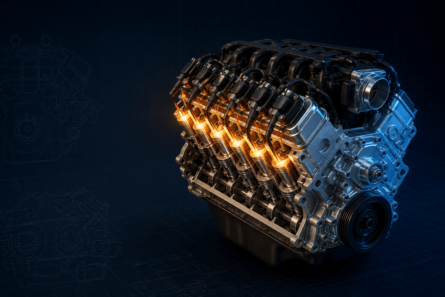
5.7 HEMI valve-cover torque workflow with 8 N·m/70 in-lb specification, middle-out crisscross order, double-ended stud and ground-strap locations.
For the cited 2005 Ram 5.7L HEMI, hand-start all valve-cover fasteners, verify the double-ended studs and ground straps are in their original positions, then tighten to 8 N·m (70 in-lb). Begin in the middle and move outward in a top-to-bottom crisscross pattern. Ignition-coil fasteners are a separate 12 N·m (105 in-lb) operation.
Valve-cover fasteners are small, but the joint is unforgiving. On the 5.7L HEMI, sealing depends on a relaxed cover, a correctly seated molded or cork/rubber gasket, sound grommets and a gradual clamp load. Cranking down a leaking corner usually bends the flange, splits the gasket or pulls a threaded insert from the cover.
The Ram procedure is unusually specific: the right ground strap belongs on the front inboard stud and the left strap on the rear inboard stud. Those details should be photographed before disassembly.
Use the controller as a disciplined work sequence: identify the exact application, map every special stud, prepare the sealing surfaces, hand-start everything and approach final torque in stages. Recheck the gasket edge before installing coils, wiring and hoses that hide it.
Interactive 5.7L HEMI valve-cover workflow
Branded downloads includedPNG and PDF exports carry the TorqueSheet logo, torquesheet.com, source-page URL, and republishing attribution request. The PDF source link is clickable.
Select each stage in order. This is an installation controller, not a substitute for the exact factory location drawing when the cover, studs or bolt count differ.
Dodge 5.7 Hemi Valve Cover Torque Diagram
| APPLICATION / ITEM | SPECIFICATION | NOTES |
|---|---|---|
| Cover bolts/studs | 8 N·m / 70 in-lb | 2005 Ram 5.7L |
| Order | Middle-out crisscross | Top to bottom |
| Coil fasteners | 12 N·m / 105 in-lb | Separate operation |
| Ground straps | Original stud locations | Do not relocate |
Correct stud placement matters because the machined ground-strap locations and coil hardware are part of the cover installation.
How to use this specification correctly
- 01
Confirm model year, engine code and cover construction. Photograph the PCV plumbing, wire clips, ground straps, coil brackets and every stud before removal.
- 02
Work on a cool engine. Disconnect the negative battery cable where the service procedure requires it, then remove covers, ducts, coils and brackets without levering against the sealing rail.
- 03
Loosen the cover gradually from the ends toward the middle. Keep bolts, studs, sealing washers and grommets in a labeled position map.
- 04
Lift the cover vertically enough to clear spark-plug tubes and valvetrain parts. Do not let old gasket debris fall into drain-back holes or the timing area.
- 05
Clean the cover groove and cylinder-head rail with non-damaging tools. Check stamped flanges for dimples, plastic covers for cracks and all sealing washers for hardening or splits.
- 06
Use non-harsh cleaners on the cover, inspect both sealing faces and set the gasket without stretching it. Hand-start the mapped bolts and double-ended studs and restore the ground straps.
- 07
Start in the middle, alternate top-to-bottom in a crisscross and work outward. Finish cover hardware at 8 N·m (70 in-lb); install coils afterward at their separate 12 N·m value.
- 08
Reconnect PCV and breather plumbing exactly as routed, return ground straps and harness supports to their original studs, and torque coil or bracket fasteners to their separate specification.
- 09
After the specified sealant cure, run the engine and inspect the entire perimeter with a light. Confirm that smoke is not residual oil on the exhaust and recheck for seepage after a full heat cycle.
Application and cover-style boundaries
The Ram procedure is unusually specific: the right ground strap belongs on the front inboard stud and the left strap on the rear inboard stud. Those details should be photographed before disassembly.
The gasket may be reused only if it has no cuts, tears or deformation in the cited procedure. In practice, replace any hardened, flattened or questionable seal while access is open.
Torque sequence and gasket installation
Use non-harsh cleaners on the cover, inspect both sealing faces and set the gasket without stretching it. Hand-start the mapped bolts and double-ended studs and restore the ground straps.
Start in the middle, alternate top-to-bottom in a crisscross and work outward. Finish cover hardware at 8 N·m (70 in-lb); install coils afterward at their separate 12 N·m value.
Reading the interactive pattern
The middle-outward strategy spreads gasket compression instead of trapping a high spot at an end. Where the factory procedure gives an explicit crisscross direction, the controller preserves it. Where it does not, the controller shows a conservative staged workflow and tells you to retain the factory location map.
Treat a target torque as the last step, not the whole repair. A fastener that reaches the number while bottomed in a blind hole or sitting on a collapsed grommet has not necessarily clamped the cover.
Common reasons a new gasket still leaks
- Relocating machined ground-strap studs
- Allowing a harness to rub through the cover
- Using harsh cleaner on the cover material
- Applying 12 N·m coil torque to 8 N·m cover bolts
- Tightening one end fully before the other
Pre-start inspection
- Gasket fully seated in every groove and corner
- Spark-plug tube seals undamaged and centered
- Sealant only at the service-manual junctions
- All bolts and studs hand-started in mapped locations
- Final pass made with an inch-pound or low-range torque wrench
- Ground straps, PCV hoses and harness clips restored
- No tools, rags or debris left near the valvetrain
- Required sealant cure time observed
Dodge / Ram 5.7L HEMI specifications can change by model year, engine, platform, wheel, and installed component. Confirm the VIN or engine identity, part numbers, fastener condition, and the current manufacturer instructions before service.
Dodge 5.7 HEMI Valve Cover Torque Diagram FAQs
What is 5.7 HEMI valve-cover bolt torque?+
The cited 2005 Ram procedure specifies 8 N·m (70 in-lb).
What is the HEMI valve-cover sequence?+
Begin in the middle and work outward in a top-to-bottom crisscross pattern.
Should the valve-cover bolts be retorqued after a heat cycle?+
Only if the exact procedure or gasket manufacturer calls for it. Some older cork/composite joints include a wait-and-repeat step; modern molded gaskets generally do not need an improvised hot retorque.
Can RTV replace the valve-cover gasket?+
Usually no. Install the specified gasket and put liquid gasket only at named corners, cap joints or semicircular plugs. Excess RTV can squeeze inside and break loose.
Can I tighten the bolts by feel?+
These values sit near the bottom of many foot-pound wrench ranges. An inch-pound or suitable low-range torque wrench gives much better control and reduces broken covers and stripped threads.
Technical sources
TorqueSheet favors engine- and component-specific manufacturer instructions over unsourced universal values.
1Mopar vehicle informationOfficial Dodge, Ram, Chrysler and Jeep model-year information lookup.↗