Ford 4.6 V8 Coil Pack Wiring Diagram: EDIS vs. Coil-on-Plug
Ford 4.6 ignition wiring guide separating early two-pack waste-spark systems from later coil-on-plug layouts, with firing order, cylinder numbering.
First identify the ignition architecture. Early Ford 4.6L applications can use two four-tower waste-spark coil packs; later applications commonly use eight coil-on-plug units and have no spark-plug wires or universal coil-pack tower layout. Both Ford owner guides cited here specify the 4.6L firing order as 1-3-7-2-6-5-4-8. On the common Modular V8 numbering convention, cylinders 1-2-3-4 are on the passenger/right bank from front to rear and 5-6-7-8 are on the driver/left bank from front to rear. Exact connector pins, wire colors and tower positions must come from the electrical manual for the VIN, model and year.
Ford used the 4.6L Modular V8 across trucks, vans, Mustangs, full-size sedans and Lincoln/Mercury vehicles for many years. The words '4.6 coil diagram' therefore describe a family of systems, not one harness. A 1997 Ford truck guide calls its 4.6L ignition electronic distributorless, while Ford's 1999 Mustang guide explicitly calls the 4.6L system coil-on-plug. That factory documentation is the essential dividing line for diagnosis.
Before unplugging anything, read the VIN year, vehicle line and engine identification, then count the ignition coils. Two multi-tower packs with eight high-tension leads indicate a waste-spark layout. Eight small coils sitting directly over the plugs indicate COP. Some packaging and transition years differ by vehicle line, so year alone is not enough.
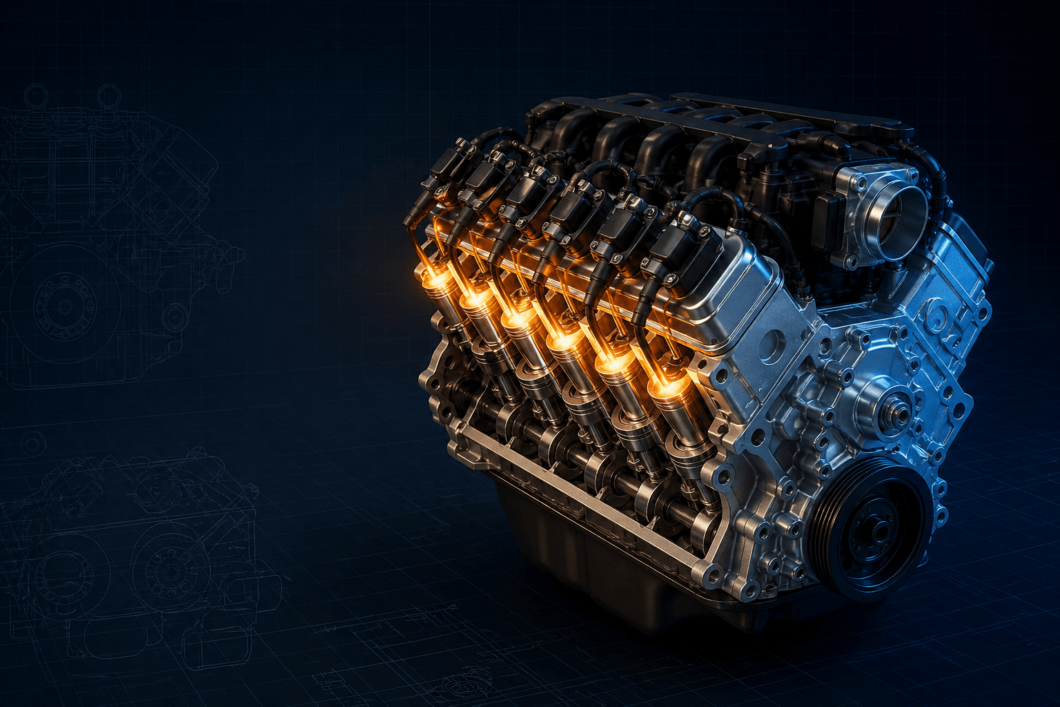
Interactive 4.6L ignition architecture map
Branded downloads includedPNG and PDF exports carry the TorqueSheet logo, torquesheet.com, source-page URL, and republishing attribution request. The PDF source link is clickable.
Use the vehicle year/model electrical manual to turn this functional map into connector-pin or tower-level wiring. Do not place wires by pack position alone.
Ford 4.6 V8 Coil Pack Wiring Diagram
| APPLICATION / ITEM | SPECIFICATION | NOTES |
|---|---|---|
| Ford firing order | 1-3-7-2-6-5-4-8 | Confirmed in official 1997 and 1999 Ford owner guides |
| Right/passenger bank | 1-2-3-4 | Front to rear on common longitudinal Modular layouts |
| Left/driver bank | 5-6-7-8 | Front to rear on common longitudinal Modular layouts |
| Waste-spark companions | 1/6, 3/5, 7/4, 2/8 | Paired 360 crank degrees apart; verify tower placement by application |
| COP layout | One coil per cylinder | Common later design; no plug-wire pairing |
A firing-order diagram is not a wiring diagram. The firing order describes combustion sequence; a waste-spark diagram additionally groups companion cylinders; a connector diagram assigns power and PCM/ignition-module control circuits. Mixing those three can create a no-start, PCM-driver damage or a catalytic-converter-damaging misfire.
How to use this specification correctly
- 01
Record VIN, model year, vehicle line, 2-valve/3-valve/4-valve configuration and any engine or harness swap history.
- 02
Identify the hardware: two four-tower coil packs and plug wires, or eight individual coils mounted over the spark plugs.
- 03
Label every existing connector and plug wire before removal. Photograph tower markings and harness routing from several angles.
- 04
Confirm cylinder numbering and the Ford-specified firing order, but retrieve the exact Ford electrical diagram before assigning a connector pin, control wire or physical tower.
- 05
With battery power isolated as directed by the service manual, inspect connectors for backed-out terminals, water, oil, green corrosion, rubbed insulation and broken locks.
- 06
Perform power, ground and control-circuit tests with the correct high-impedance meter or scope. Never use a conventional incandescent test lamp on a PCM driver.
- 07
After repair, clear codes, run the engine under the conditions that produced the fault and check misfire data. Confirm no raw-fuel odor, flashing MIL or overheated catalyst.
Cylinder numbering and firing order
On the common longitudinal Ford Modular layout, the passenger-side bank is cylinders 1 through 4 from front to rear; the driver-side bank is 5 through 8 from front to rear. Ford specifies the 4.6L firing order 1-3-7-2-6-5-4-8 in both the 1997 F-150 and 1999 Mustang owner guides cited below.
Do not confuse that sequence with the physical left-to-right position of towers on a coil pack. The molded tower arrangement can be packaged differently, and the coil packs themselves can be mounted or swapped in different positions after an engine conversion.
Early two-pack waste-spark system
A waste-spark coil fires two cylinders at the same time: one plug fires on the compression stroke and its companion fires on the exhaust stroke. From the Ford firing order, the companion groups are 1 with 6, 3 with 5, 7 with 4, and 2 with 8. Those pairings describe the two ends of each secondary coil; they do not by themselves identify which molded tower occupies which corner.
Each pack also contains primary windings controlled by the ignition module or PCM strategy used on that application. Obtain the year/model electrical and vacuum troubleshooting manual before probing the multi-pin connector. A diagram copied from another chassis can reverse control assignments even when the pack looks identical.
Later coil-on-plug system
COP eliminates the shared secondary cable: each cylinder has a dedicated coil connected directly to its spark plug. A common feed supplies the coils, while the controller switches or commands individual primary circuits according to the crankshaft and camshaft signals. Exact feed splice, fuse, capacitor, connector pin and control-wire color vary by vehicle.
Ford TSB 05-22-8 warns that many COP coils returned for warranty were not faulty and directs technicians to distinguish primary and secondary causes. A misfire code identifying one cylinder is a starting point, not automatic proof that its coil has failed.
How to diagnose without damaging the PCM
- Verify battery voltage and charging-system condition before interpreting weak-spark symptoms.
- Read P030x misfire and P035x primary-circuit codes with freeze-frame data.
- Inspect coil boots for carbon tracking, oil or coolant in plug wells and damaged springs.
- Check the common ignition-power feed under load using the exact circuit diagram.
- Use an oscilloscope or manufacturer-approved test for PCM control pulses; do not short a driver to power or ground.
- Swap a suspect COP only as a controlled test and confirm that the fault follows; do not move multiple parts at once.
- Stop running the engine if the MIL flashes, because continued misfire can overheat the catalytic converter.
Why a universal color chart is unsafe
Ford changed harness colors, splice locations, connector keys, fuse assignments and PCM terminals across Crown Victoria, Grand Marquis, Town Car, Mustang, F-150, Expedition, E-Series and other 4.6L platforms. Production revisions and replacement harnesses add more variation.
Use color only as a confirmation after locating the circuit by connector view and pin number in the VIN-matched manual. When a swap combines an engine, controller and body harness from different donors, document all three before energizing the circuit.
Ford 4.6L Modular V8 specifications can change by model year, engine, platform, wheel, and installed component. Confirm the VIN or engine identity, part numbers, fastener condition, and the current manufacturer instructions before service.
Ford 4.6 V8 Coil Pack Wiring Diagram: EDIS vs. Coil-on-Plug FAQs
What is the Ford 4.6 V8 firing order?+
Ford's cited 1997 and 1999 owner guides specify 1-3-7-2-6-5-4-8 for their 4.6L applications.
Which cylinders share a coil on the early 4.6 waste-spark system?+
The functional companion pairs are 1/6, 3/5, 7/4 and 2/8. Verify the physical tower locations in the exact vehicle electrical manual.
Does every Ford 4.6 have two coil packs?+
No. Early applications can use multi-tower packs, while many later 4.6L engines use eight coil-on-plug units.
Can I wire a COP by matching wire color from another Ford?+
No. Confirm connector face, pin number, circuit function and year/model schematic; colors and PCM terminals vary.
Does a P035x code prove the coil is bad?+
No. It indicates a primary-circuit fault area that can involve power, connector, wiring, the coil or controller. Ford's COP bulletin emphasizes proper diagnosis before replacement.
Technical sources
TorqueSheet favors engine- and component-specific manufacturer instructions over unsourced universal values.
11997 Ford F-150 Owner Guide - 4.6L engine dataFord lists the 4.6L firing order as 1-3-7-2-6-5-4-8 and identifies the application as an electronic distributorless ignition system.↗21999 Ford Mustang Owner Guide - 4.6L ignition specificationFord lists the same 1-3-7-2-6-5-4-8 firing order while identifying the 1999 Mustang 4.6L system as coil-on-plug, documenting the architecture change.↗3Ford TSB 05-22-8 - Coil-on-plug diagnostic guidanceFord's bulletin identifies 4.6L-era Crown Victoria, Mustang, E-Series, Expedition, F-150, Town Car and Grand Marquis applications that use coil-on-plug ignition and gives COP diagnostic cautions.↗