Ford 5.4 3V Timing Chain Alignment: Chains, Phasers and Verification
Ford 5.4 3V timing-chain alignment guide covering engine identification, colored links, crank and cam-phaser references, tensioner release.
The Ford 5.4L 3V uses two primary timing chains, one for each cylinder bank, and a variable-cam-timing phaser on each camshaft. Alignment requires the exact workshop-manual crank position, the designated colored chain links placed at the crank-sprocket and phaser timing marks, correct left/right guides and tensioners, and phasers fully seated on their camshaft alignment pins. Ford warns that incorrect phaser alignment or retaining-bolt torque can deform or shear the pin and cause rattle, rough running or a check-engine light.
A correct 5.4 3V timing job begins by ruling out the 2-valve and 4-valve engines. The 3V version has a single overhead camshaft and a VCT phaser on each bank. Its two chains look simple compared with a DOHC system, but phaser seating, oil-controlled timing and valve-to-piston clearance make shortcuts expensive.
Internet diagrams often combine a valid chain sketch with an unsupported tooth count, mirrored bank labels or a crank position taken from another modular engine. This guide stays within Ford's published evidence: it explains the component relationship and Ford's phaser-installation warning, then directs the installer to the exact WSM for colored-link and service-position details.
Ford also warns against diagnosing every 5.4 3V rattle as a stretched chain. Its bulletins distinguish injector, lash-adjuster, phaser and VCT-solenoid behavior and use oil condition, temperature and scan data before parts replacement.
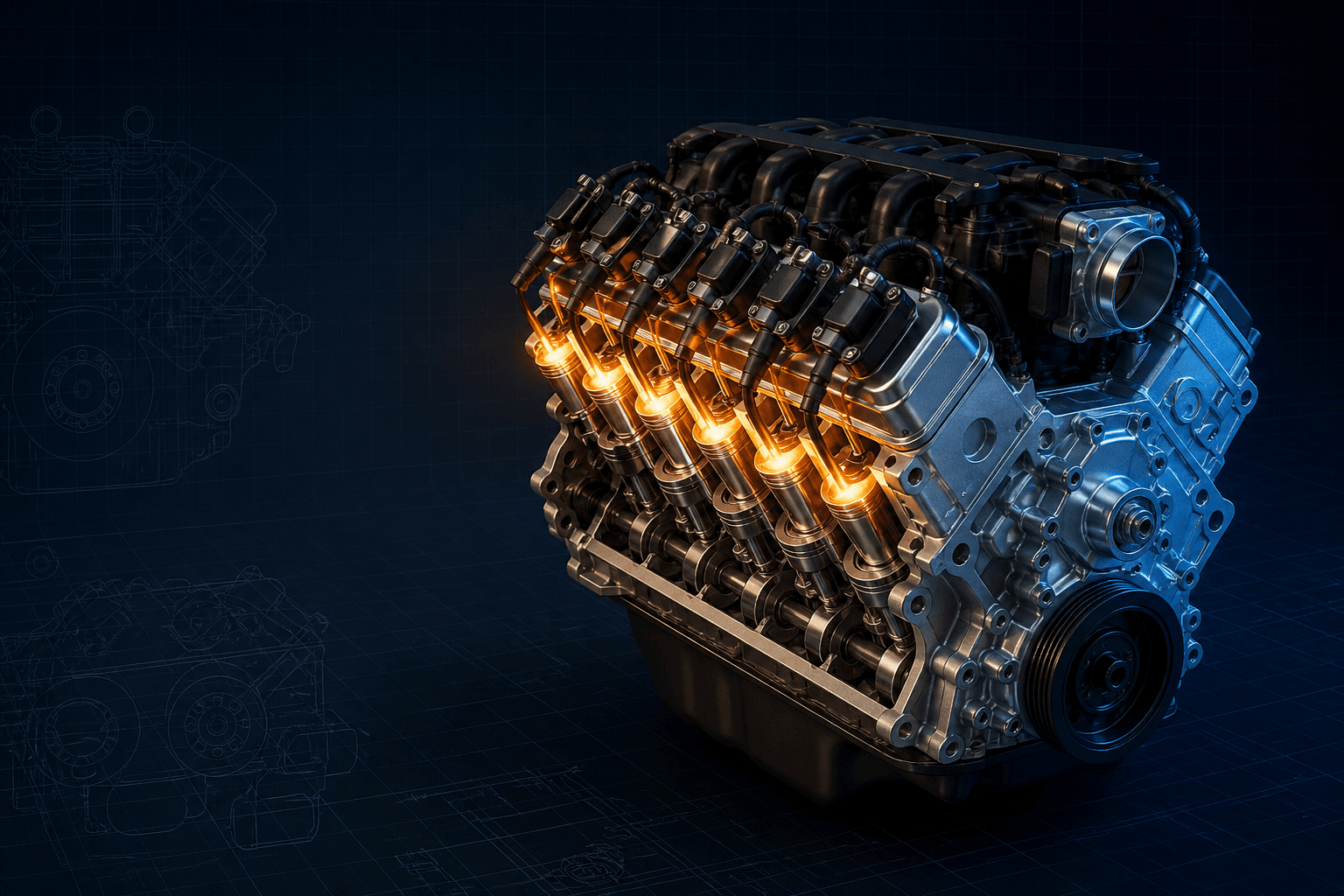
Interactive 5.4L 3V timing architecture
Branded downloads includedPNG and PDF exports carry the TorqueSheet logo, torquesheet.com, source-page URL, and republishing attribution request. The PDF source link is clickable.
Functional bank map for identifying components. Select the exact Ford workshop diagram before assigning individual colored links or releasing tensioners.
Ford 5.4 3v Timing Chain Alignment Diagram
| APPLICATION / ITEM | SPECIFICATION | NOTES |
|---|---|---|
| Architecture | SOHC 3-valve; one VCT cam phaser per bank | Not interchangeable with 5.4L 2V/4V diagrams |
| Timing drive | Two primary chains | One crank-to-cam chain for each bank |
| Phaser bolt | 40 N·m (30 lb-ft) + 90° | Ford 3V job aid; use new fastener if WSM requires |
| Alignment references | Marked links to crank and phaser marks | Exact link identity comes from vehicle WSM/chain instructions |
| Final check | Hand rotation, mechanical recheck and scan data | Do not judge only by colored-link position after rotation |
Ford's 2015 3V cam-phaser job aid specifies that the phaser retaining bolt is tightened in two stages: 40 N·m (30 lb-ft), then an additional 90 degrees. The job aid explicitly says it does not replace the Workshop Manual, so this page does not invent a universal colored-link count or crank-clock position. Those details must come from the WSM procedure for the exact vehicle, year and installed timing set.
How to use this specification correctly
- 01
Confirm the engine is a 5.4L 3V by VIN, model year, build date and cam-cover/valvetrain identification; obtain the matching Ford WSM section.
- 02
Record diagnostic codes, commanded/actual cam behavior, hot-idle symptoms, oil level, viscosity and filter condition before disassembly.
- 03
Disconnect the battery and remove the front-cover components with the vehicle-specific procedure; protect open oil passages and the oil pan from debris.
- 04
Set the crankshaft at the WSM service position before removing tension. Do not rotate crankshaft or camshafts independently unless the procedure explicitly permits it.
- 05
Compress and pin each tensioner by its specified method. Mark LH and RH guides, arms and chains so bank-specific parts cannot be swapped.
- 06
Inspect chain links, guides, tensioner bores, crank sprocket, phaser teeth, cam alignment pins and oil-control passages. Replace damaged parts as a matched application set.
- 07
Install each chain with its designated marked links at the WSM crank-sprocket and phaser marks, maintaining tension on the drive side while slack remains at the tensioner arm.
- 08
Seat each phaser squarely over its camshaft alignment pin. Use the required holding tool; never pull a misaligned phaser into position with the retaining bolt.
- 09
Apply the WSM fastener/reuse rules. Ford's phaser job aid gives 40 N·m (30 lb-ft) plus 90 degrees for the phaser bolt, performed without loading the chain as a counterhold.
- 10
Verify every mark, guide and trigger-wheel orientation, then release tensioners in the prescribed order. Hand-rotate the crank in the normal direction and stop if resistance is felt.
- 11
Recheck mechanical timing/tool fit, complete sealing and oil priming, then monitor startup oil pressure, noises, DTCs and VCT data.
How the 5.4L 3V system is arranged
A crankshaft sprocket drives one long chain to the cam phaser on each cylinder bank. A fixed guide controls the drive span while a hydraulic tensioner and pivoting arm control slack. The phaser changes cam angle under PCM command through an oil-control solenoid.
Because both banks share the crank sprocket but have separate chains and phasers, one correctly aligned bank does not prove the other is correct. Treat left and right components as separate assemblies and verify both before tensioners are released.
Colored links and timing marks
Marked chain links are installation references. The chosen links align with stamped, etched or dimpled references on the crank sprocket and each cam phaser exactly as the WSM illustration shows. Replacement-chain colors can differ, so color name alone is not enough.
Once the engine is rotated, colored links generally do not return to all sprocket marks after two crank revolutions. Final verification uses crank/cam mechanical references and specified tools, not the expectation that paint marks immediately reappear.
Protecting the cam-phaser alignment pin
Ford's 3V job aid shows scoring, pin-hole deformation, fracture and complete alignment-pin shear from improper installation. The phaser must sit fully against the camshaft in the correct indexed position before bolt tightening begins.
Do not use the bolt to draw the phaser over a pin that is not engaged. Hold the camshaft/phaser with the approved tool, keep the torque wrench and angle gauge controlled, and follow bolt replacement and lubrication instructions from the WSM.
Do not replace timing parts from noise alone
Ford TSB 06-19-8 says these engines produce several normal or easily confused sounds. Injector tick, lash-adjuster noise, hot-idle VCT knock and brief startup rattle have different test conditions and repair paths.
TSB 12-7-10 addresses intermittent hot rattle/rough idle with oscillating cam timing on specified applications and directs scan-tool monitoring of VCT duty-cycle and cylinder-head temperature before replacement of both VCT oil-control solenoids. That bulletin is not proof that every rattle needs solenoids; it is an application-limited diagnostic path.
Assembly and startup checklist
- Correct 5.4L 3V vehicle WSM open
- Both banks and components labeled LH/RH
- Crank set to exact service position
- Marked links matched to the illustrated sprocket/phaser marks
- Phasers fully seated on undamaged alignment pins
- Cam/phaser holding tool used
- Guides and tensioners installed by bank and released only after mark check
- Trigger wheel orientation confirmed
- Engine turns smoothly by hand
- Oil system primed as directed
- DTCs, commanded/actual VCT and startup sound rechecked
Ford 5.4L 3-Valve Modular V8 specifications can change by model year, engine, platform, wheel, and installed component. Confirm the VIN or engine identity, part numbers, fastener condition, and the current manufacturer instructions before service.
Ford 5.4 3V Timing Chain Alignment: Chains, Phasers and Verification FAQs
How many timing chains does a Ford 5.4 3V have?+
It has two primary chains, one from the crankshaft to the cam phaser on each bank.
What is the Ford 5.4 3V cam-phaser bolt torque?+
Ford's 3V job aid specifies 40 N·m (30 lb-ft), then an additional 90 degrees, while requiring the WSM procedure to be followed.
Can the phaser bolt pull the phaser onto the cam pin?+
No. The phaser must be correctly aligned and seated first. Pulling it into place can deform or shear the alignment pin.
Should the colored links line up after two revolutions?+
Not necessarily. They are assembly references and may require many revolutions to repeat. Use the WSM mechanical verification method.
Does every 5.4 3V startup rattle mean the chain is stretched?+
No. Ford describes several possible or normal noises. Diagnose oil supply, tensioners, phasers, lash adjusters, VCT solenoids and correlation data before choosing a repair.
Is this diagram valid for a 5.4 2V or 4V?+
No. Those engines have different timing architecture and procedures.
Technical sources
TorqueSheet favors engine- and component-specific manufacturer instructions over unsourced universal values.
1Ford 3V cam-phaser installation job aidFord documents alignment-pin damage from incorrect 4.6L/5.4L 3V phaser installation and requires correct alignment plus a two-stage retaining-bolt procedure.↗2Ford TSB 12-7-10 - 5.4L 3V VCT rattle and rough-idle diagnosisFord identifies affected 5.4L 3V F-150, Super Duty, Expedition, Navigator and Mark LT applications and uses scan-data diagnosis before VCT-solenoid replacement.↗3Ford TSB 06-19-8 - 4.6L/5.4L 3V timing-area noise diagnosisFord distinguishes the 4.6L 3-valve architecture and directs technicians through application-specific diagnosis rather than treating every timing-area noise as a failed chain.↗