Chevy LS1 Oil Passage Diagram: Pump, Filter and Galleries
LS1 oil-flow diagram showing pickup, crank-driven gerotor pump, pressure relief, pan/filter passages, main gallery, cam and main bearings, lifters, pushrods.
A production wet-sump LS1 draws oil through the pan pickup into the crankshaft-driven gerotor pump at the front cover. Pump output is routed through the pan/block interface to the full-flow filter, then into the block's main oil gallery. Branch passages feed the main and cam bearings, crankshaft/rod bearings, lifters and valvetrain before oil drains through the heads and block back to the pan.
LS1 oil pressure begins with pump filling. The front-mounted gerotor cannot move oil reliably if the pickup connection draws air, the tube is cracked, the pan level is wrong, or the pickup-to-pan clearance is unsuitable. A pressure problem after a pan swap therefore deserves a suction-side check before the pump is condemned.
After the pump raises pressure, oil must cross the correct pan/block/filter passages. This is where swap parts matter. An F-body pan, Corvette pan, remote-filter adapter and oil-cooler block-off may use the same engine block but route oil through different castings and seals. The internal gallery drawing remains useful only after those external interfaces are verified.
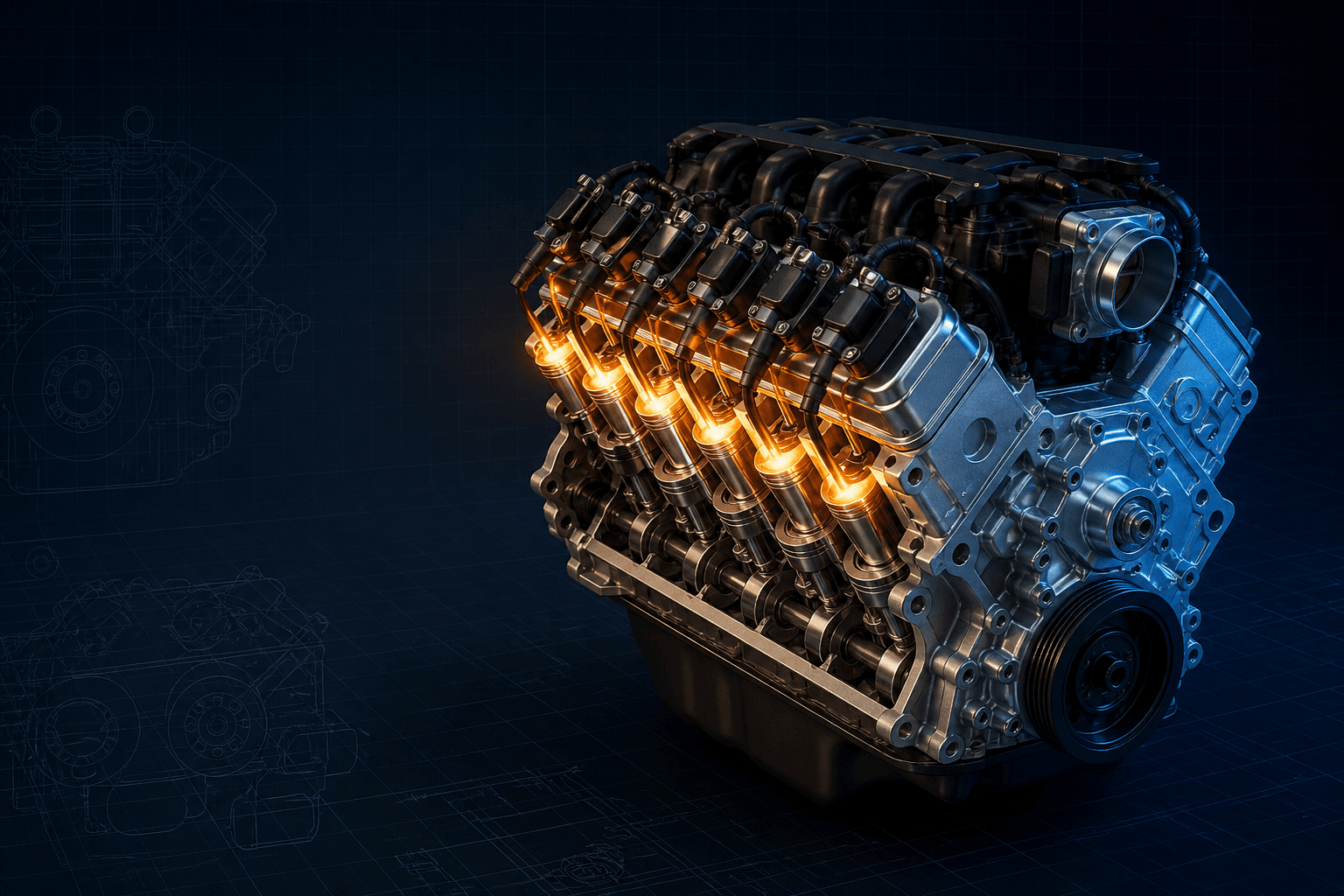
Interactive LS1 lubrication-flow diagram
Branded downloads includedPNG and PDF exports carry the TorqueSheet logo, torquesheet.com, source-page URL, and republishing attribution request. The PDF source link is clickable.
Follow the wet-sump functional path. Pan/filter and cooler routing must be replaced with the actual application's hardware map.
Chevy Ls1 Oil Passage Diagram
| APPLICATION / ITEM | SPECIFICATION | NOTES |
|---|---|---|
| Pump type | Crank-driven gerotor | Mounted around the crank snout behind the front cover |
| Pump inlet | Pan pickup tube | Pickup O-ring and tube sealing are critical |
| Primary conditioning | Full-flow oil filter | Filter location/path depends on pan and adapter |
| Block distribution | Main oil gallery | Feeds bearing and lifter branches |
| Top-end delivery | Lifters → hollow pushrods → rockers | Drainback returns through head/block openings |
The functional engine galleries are shared, but the external path through pickup, pan, filter mount, cooler or remote adapter changes with F-body, Corvette and swap oil pans. Dry-sump LS-family diagrams must not be used for a wet-sump LS1 without mapping every added stage.
How to use this specification correctly
- 01
Identify the engine casting, vehicle or swap application, oil pan part number, pickup, windage tray, filter mount, cooler/adapter and pressure-sender location.
- 02
Confirm pickup depth and clearance using the pan or swap-kit maker's procedure; verify the pickup tube is supported and the correct new O-ring is installed without damage.
- 03
Trace pump outlet to filter inlet and filter outlet to the block gallery on the actual pan/adapter. Never assume two visible ports can be joined in either direction.
- 04
Before first start after internal or pan work, pre-lubricate with the GM-approved method for the assembly and verify pressure with a known-good mechanical gauge when diagnosis requires it.
- 05
If pressure is abnormal, separate gauge/sender error, oil level/viscosity, pickup aeration or restriction, relief leakage, filter/bypass faults, gallery leakage and excessive bearing clearance.
Pickup and gerotor pump
Oil enters through a screened pickup in the sump and passes through the pickup tube and its sealing O-ring. The crankshaft turns the concentric gerotor set. Pump filling depends on a sealed inlet and suitable pickup submersion; aerated oil reduces effective delivery and can produce pressure fluctuation.
The pump's regulating function limits output pressure by recirculating excess flow under the designed condition. A stuck valve, worn housing, damaged gerotor, incorrect front-cover alignment or debris can affect output, but each must be distinguished from a leaking pickup seal.
Filter and pan/block interface
Pump output travels through machined passages associated with the block and oil-pan/filter assembly. The full-flow filter removes contaminants before oil enters the main distribution gallery. Depending on the application, cooler, bypass or remote-filter hardware may be included in this section.
A gasket or adapter installed in the wrong orientation can cover a port or connect pressure and return incorrectly. Compare port direction and seal locations with the exact Chevrolet or kit instructions before cranking.
Main, cam and connecting-rod bearings
Filtered oil enters the block's main gallery and branches to the main bearings and cam-bearing/lifter circuits. Drillings in the crankshaft carry oil from the main journals to the connecting-rod journals. Bearing clearance, journal condition and plug integrity control how much leakage the pump must supply.
Low hot-idle pressure can reflect excessive internal clearance even when the pump is capable. Conversely, a high reading at one point does not prove that every remote bearing or valvetrain branch is receiving flow.
Lifters, pushrods and rocker arms
The lifter galleries supply the hydraulic roller lifters. Metered oil passes through the hollow pushrods to the rocker arms and valve tips. Oil then drains through cast openings in the heads and valley/block toward the sump.
Sludge, incorrect lifters or pushrods, blocked drainback, excessive sealant and incompatible head/block parts can alter top-end delivery. Diagnose the branch rather than increasing pressure indiscriminately.
Common LS1 oiling mistakes
- Reusing a flattened or cut pickup-tube O-ring.
- Combining a pan and pickup that do not share the specified depth and support.
- Reversing remote-filter or cooler lines.
- Leaving an adapter, gallery or cooler port open or incorrectly blocked.
- Using a dry-sump schematic to plumb a wet-sump conversion.
- Assuming the dashboard sender proves actual pressure without a test gauge.
Chevrolet 5.7L LS1 specifications can change by model year, engine, platform, wheel, and installed component. Confirm the VIN or engine identity, part numbers, fastener condition, and the current manufacturer instructions before service.
Chevy LS1 Oil Passage Diagram: Pump, Filter and Galleries FAQs
Does an LS1 oil pump sit in the oil pan?+
No. The gerotor pump surrounds the crank snout at the front of the engine; a pickup tube connects it to the pan sump.
Can a pickup O-ring cause low LS1 oil pressure?+
Yes. A damaged, hardened, pinched or incorrect O-ring can admit air into the pump inlet and reduce delivery.
Does oil go through the filter before the engine galleries?+
In the production full-flow circuit, pump output is routed through the filter path before entering the main distribution gallery, subject to the application's bypass strategy.
How does oil reach LS1 rocker arms?+
The lifter receives gallery oil and meters it through the hollow pushrod to the rocker arm.
Can I copy Corvette oil routing for an F-body LS1 swap?+
Not without verifying the pan, pickup, filter, cooler and adapter. Internal galleries are related, but the external oil-management hardware differs.
Technical sources
TorqueSheet favors engine- and component-specific manufacturer instructions over unsourced universal values.
1Chevrolet Performance LS1 installation-guide referenceChevrolet identifies LS1 Engine Installation Guide 88959384 as the factory reference for LS1 swaps, parts and technical explanations.↗2Chevrolet Performance LS oil-pan and oil-pump catalogChevrolet distinguishes F-car, Corvette, circle-track, wet-sump and dry-sump oiling hardware rather than treating every LS oil path as interchangeable.↗